Be part of the future with us!
Register now for our online product launch event on May 23rd.


NanoAvionics First and Second Generation Electrical Power Systems (EPS 1.0 and EPS 2.0) are designed to meet the newest nano and microsatellite market demand, requiring high power in a small size.
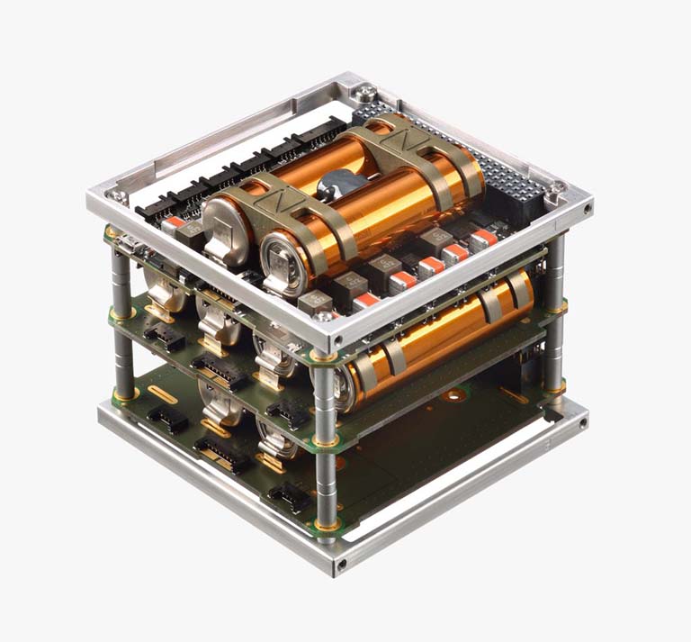
The EPS is a subsystem that manages the power collection and distribution in the satellite with an integrated Battery Management System (BMS). All subsystem and payload power supply are controlled via the EPS and all of the output channels can be switched on and off autonomously or by ground command. The EPS stores generated energy in onboard Lithium-Ion batteries. To ensure a safe battery working environment the EPS is integrated with battery heaters and battery balancing functions.
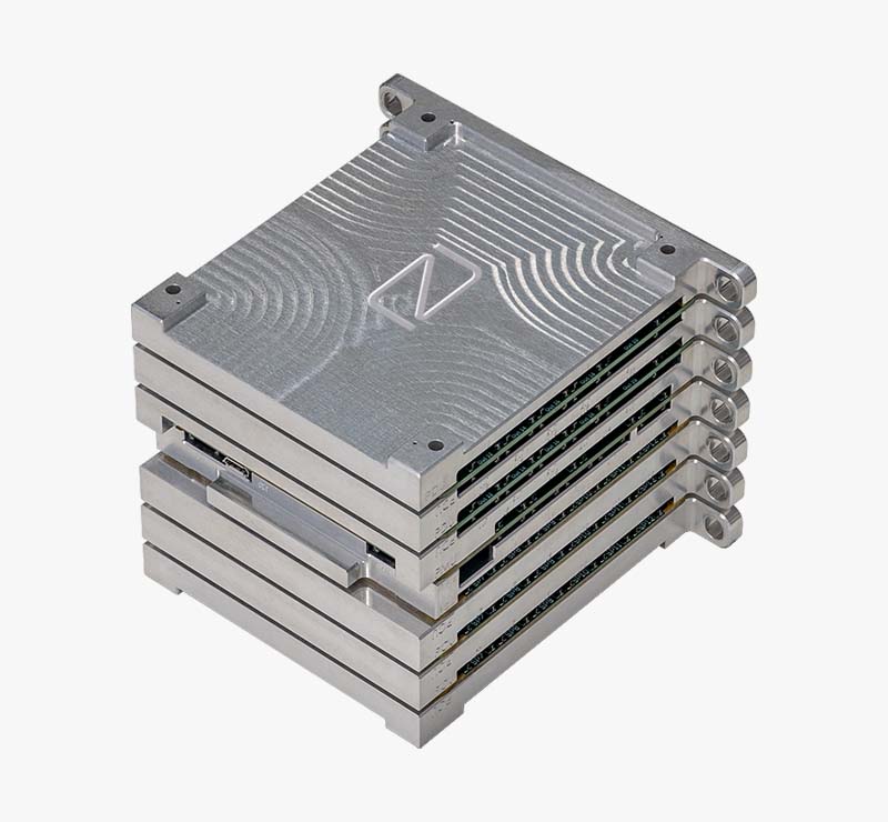
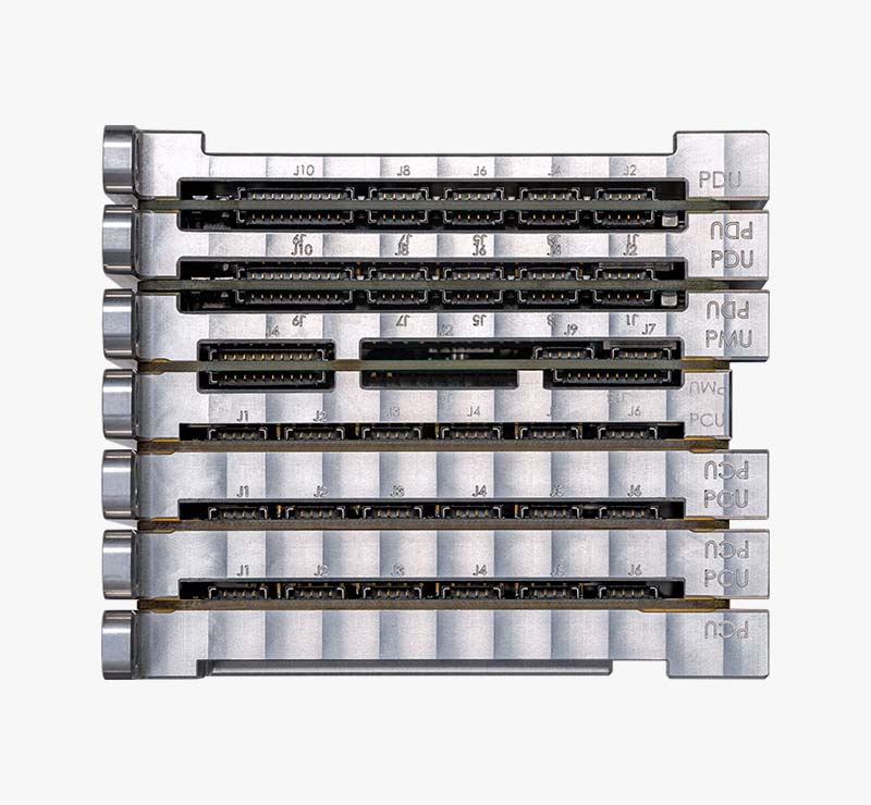
Modular architecture allows to scale EPS 2.0 to any project requirements without stretching specs or flying with excess hardware. This is achieved by separating EPS 2.0 into four main blocks: PCU, PMU, PDU, and PSU. Depending on project and mission requirements, a combination of these boards can be adjusted, so the most efficient solution can be achieved.
NanoAvionics First and Second Generation Electrical Power Systems (EPS 1.0 and EPS 2.0) are designed to meet the newest nano and microsatellite market demand, requiring high power in a small size.
The EPS is a subsystem that manages the power collection and distribution in the satellite with an integrated Battery Management System (BMS). All subsystem and payload power supply are controlled via the EPS and all of the output channels can be switched on and off autonomously or by ground command. The EPS stores generated energy in onboard Lithium-Ion batteries. To ensure a safe battery working environment the EPS is integrated with battery heaters and battery balancing functions.
Modular architecture allows to scale EPS 2.0 to any project requirements without stretching specs or flying with excess hardware. This is achieved by separating EPS 2.0 into four main blocks: PCU, PMU, PDU, and PSU. Depending on project and mission requirements, a combination of these boards can be adjusted, so the most efficient solution can be achieved.
Highlight Features:
Main Specifications:
Outputs:
Inputs:
Configuration Options:
Power Supply System EPS 2S1P Configuration
Max Unregulated Output Power 25 W
Max Charging Power 10 W”
Power Supply System EPS 2S2P Configuration
Max Unregulated Output Power 50 W
Max Charging Power 20 W”
Power Supply System EPS 2S3P Configuration
Max Unregulated Output Power 75 W
Max Charging Power 30 W”
Power Supply System EPS 2S4P Configuration
Max Unregulated Output Power 100 W
Max Charging Power 40 W”
Power Supply System EPS 2S5P Configuration
Max Unregulated Output Power 125 W
Max Charging Power 50 W”
Power Supply System EPS 2S6P Configuration
Max Unregulated Output Power 150 W
Max Charging Power 60 W”
Power Supply System EPS 2S7P Configuration
Max Unregulated Output Power 175 W
Max Charging Power 70 W”
Highlight Features:
Main Specifications:
Outputs:
Inputs: